Limits
Note
Limits are typically set to protect the controller hardware, the motor, or other system elements from damage. They should only be changed by a knowledgeable system engineer. It is usually best to change them incrementally and observe the result before continuing.
Voltages
The following should be considered when setting up a new system:
- Nominal battery voltage
- Undervoltage warning limit
- Severe undervoltage (shutdown) limit. Note that the controller will not power on unless input voltage is at least as high as the shutdown limit.
- High Voltage Limit determines when the controller protects itself against unsually high input voltage.
Temperatures
The controller can cut back power to protect the hardware from damage due to over-temperature. Refer to:
- Controller Temperature Limiting for the on-board sensor
- Motor Temperature Limiting for the optional motor temperature sensor input
Controller Temperature Limiting
An onboard sensor measures the temperature of the controller near the drive electronics. As the temperature rises near the limit, the controller will indicate a high temperature condition and automatically reduce power. When the temperature decreases, output power will be restored and the high temperature indication will clear.
The temperature threshold is set in configuration register 0x0316
If the temperature increases to the limit, a fault code 0x31 is reported.
Power cutbacks start when the temperature is 8 degress C below the limit, unless Early Temperature Cutback is enabled, in which case the cutback starts 32 degrees below the limit.
Motor Temperature Limiting
Applies to
Version 1.7.2 and higher
When wired to a temperature sensor in the motor, the controller's ANALOG IN input monitors the sensor. There are two temperature thresholds. The first one causes the motor current to be reduced when the threshold is exceeded. The second (higher) limit will cause the motor to stop, report a fault, and require a key switch cycle before the motor will run again.
Configure the following registers to enable the temperature sensor.
- EEPROM Address 0x0392.0x92 Set to 0x60 to configure ANALOG IN (GPIO2) as an analog input
- EEPROM Address 0x0323 Bit 7: (motor_therm) 1 = ANALOG IN determines current limit
threshold (cur_lb or cur_ub) - EEPROM Address 0x034E (cur_time) Persistance / ramp time for cur_lb / cur_ub transitions, 40ms resolution.
- EEPROM Address 0x0321 (cur_lb) Lower current limit threshold
- EEPROM Address 0x0322 (cur_ub) Upper current limit threshold
- EEPROM Address 0x0315 (hi_tcol) ANALOG IN voltage for current limit change, 19.5mV resolution
- EEPROM Addr 0x035E (cfr_opts9) Bit 0: ANALOG IN invert. 0 = excessive temperature when ANALOG IN voltage is less than threshold 1 = excessive temperature when ANALOG IN voltage is greater than threshold
- EEPROM Address 0x035C (ina1_type) set upper nibble to '1' to enable ANALOG IN as a temperature 'stop' signal
- EEPROM Address 0x039B (ANALOG IN_temp_stop) ANALOG IN voltage for 'stop' functionality, 19.5 mV resolution. When ANALOG IN is configured as a 'stop', the fault code 0x32 will be generated upon assertion of 'ANALOG IN stop'. This condition is 'latched' and will require a key switch to recover.
Motor Current Limiting
Applies to
Version 1.7.8 and higher
Setting limits on the output current of the controller can prevent damage to the motor or other parts of the system. The system often is designed with a 'continuous' current rating, which is the amount of current that the drive can accept for long periods of time, and a shorter 'peak' current that provides extra power, for example, when starting up the motor. The key configuration parameters are described below.
Current Limit Lower Bound
The 'LB' is typically set to the desired continuous-current rating of the system. See Current Lower Boundary for more information.
Current Limit Upper Bound
The 'UB' is typically set to the desired 'surge current' rating of the system. See Current Upper Boundary for more information.
Current Limit Time and Units
The 'CT' represents the transition time between UB and LB, and can be set in seconds or minutes. The way the CT affects the current limit transitions depends on the Current Limiting Mode as described below. See Over_Current Timeout for more information.
Current Limit Mode
The Mode determines how the Lower Bound (LB), Upper Bound (UB), and Time (CT) are used to manage the motor current. In 'Step' modes, the transition between states (bounds) happens immediately. In 'Incremental' modes, the transition happens over a period of time. See Current Limit_Config for more information.
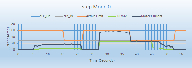
Step Mode 0
At the start of drive, current is limited to UB for the duration of CT, then the limit drops to LB until throttle is idle.
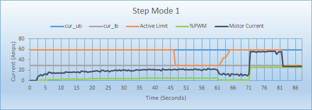
Step Mode 1
Limit to UB unless it exceeds LB/2 for CT, then limit to LB but linearly recover toward UB over several seconds.
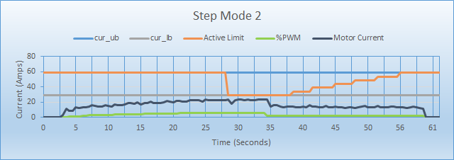
Step Mode 2
Limit to UB unless it exceeds LB/2 for CT, then limit to LB but linearly recover toward UB over a period equal to 2 x CT.
Motor Temperature
Limit to UB unless motor temperature is above the threshold for CT, then step the limit to LB but linearly recover toward UB over a period equal to 2 x CT. See section "External Motor Temperature".
Incremental Mode 0
Limit to UB unless current exceeds LB/2, then decay toward LB at a rate of 1/CT and recover toward UB over several seconds.
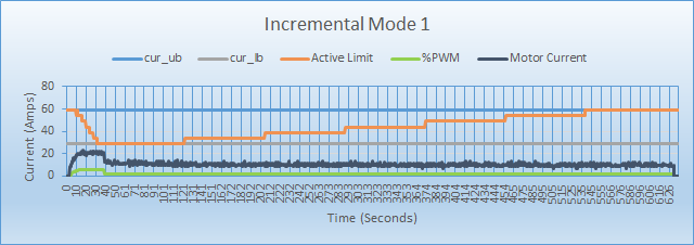
Incremental Mode 1
Limit to UB unless current exceeds LB/2, then decay toward LB at a rate of 1/CT and recover toward UB at a 30 minute rate.
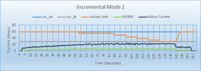
Incremental Mode 2
Limit to UB unless current exceeds LB/2, then decay toward LB proportional to (excess measured current / CT) and recover toward UB at over several seconds.
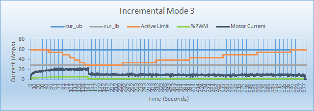
Incremental Mode 3
Limit to UB unless current exceeds LB/2, then decay toward LB proportional to (excess measured current / CT) and recover toward UB at a 30 minute rate.
Incremental Mode 4
Limit to UB unless current exceeds LB/2 for CT, then decay toward LB proportional to (excess measured current / CT) and recover toward UB at a 30 minute rate.
Incremental Mode 5
Limit to UB unless current exceeds LB/2 for CT, then decay toward LB proportional to (excess measured current / CT) and recover toward UB at a 30 minute rate.
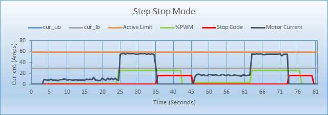
Step Stop Mode
Limit to UB unless current exceeds LB for CT, then stop the motor until throttle returns to deadband.
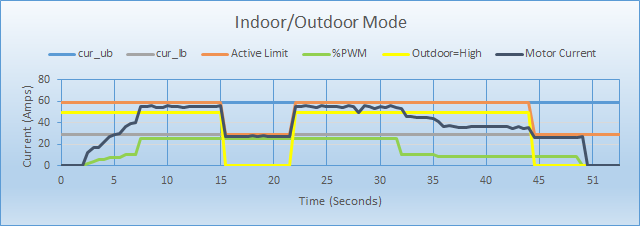
In/Out Mode
LB applies when controller is in "Indoor" mode; UB applies when controller is in "Outdoor" mode.
Current Limiting Examples
The graphs below show the behavior of the various current limiting modes, using a Lower Bound of 29 amps and an Upper Bound of 59 amps. Current Limit Time was set to 10 seconds except for Incremental mode 0 & 1 which used 20 seconds.
Step Mode 0
The current limit is UB for the duration of CT, then the limit switches to LB regardless of how much current is being used. The limit stays at LB until the motor is stopped. The orange line shows that the limit drops to LB after the time limit regardless of how hard the motor runs. The second time the motor was run much harder and the the current was held to UB for 10 seconds then it was reduced to LB.
Step Mode 1
This mode will switch to LB when the current is > LB/2 for CT. The recovery is a fast linear recovery of .64 seconds per step from LB to UB. Notice how the current recovers in about 3.84 seconds. In these examples the number of steps from LB to UB is 6 and the rate is .64 seconds per step.
Step Mode 2
This mode will switch to LB when the current is > LB/2 for cur_time just like Step Mode 1. However the recovery is a fixed time equal to 2 * CT. Notice how the current recovers in 20 seconds. The CT is 10 seconds so the recovery is 20 seconds.
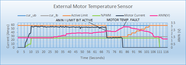
External Motor Temperature
This mode reads the ANALOG IN voltage as a temperature sensor. See Motor Temperature Limit for more detail. You can configure the controller to handle a temperature signal with either a positive or negative response direction. The voltage ranges are also adjustable. This example was set up as a positive sensor using a potentiometer to provide 0-5V to the ANALOG IN input. The the current is limited when the ANALOG IN voltage is above 2.05V. When the temperature is above 2.80V the unit throws a motor temperature fault and stops the motor.
Incremental Mode 0
This mode provides a decrease in current over a time period equal to cur_time with a rapid recovery. The cur_time was set to 20 seconds for this example. Notice the current falls to cur_lb after dropping for about 20 seconds. The recovery is one step every .64 seconds or 6 * .64 or 3.84 seconds.

Incremental Mode 1
This mode provides a decrease in current over a time period equal to CT with a slow recovery. The CT was set to 20 seconds for this example. Notice the current falls to LB after dropping for about 20 seconds. The recovery is one step every 82 seconds.
Incremental Mode 2
This mode decreases current one step per each CT period with a fast recovery. The current is decreased by one step every CT interval that the current is > LB/2. The CT was set to 10 seconds for this example. The recovery is one step every .64 seconds or 6 * .64 or 3.84 seconds.
Incremental Mode 3
This mode decreases current one step per each CT period with a slow recovery. The current is decreased by one step every CT interval that the current is > LB/2. The CT was set to 10 seconds for this example. The recovery is one step every 82 seconds.
Step Stop Mode
This mode stops the motor after the current has been above LB for CT. A stop code of 0x10 is visible in status message FF03 byte 7. Once the throttle is idle the stop code clears and the motor can be operated again.
Indoor Outdoor Mode
This mode simply uses UB as a limit when the outdoor mode is active and LB when indoor mode is active.
Speed
When the controller is able to measure motor RPM (eg brushless motors) it can implement an RPM limit. On brushed motors there is a PWM limit that is available. Both brushless and brushed motors are configured with Register 038C. Speed limit re-scaling is achieved by modifying the Max Speed.