Wiring Digital Inputs
Drive Mode Selector Switch Wiring
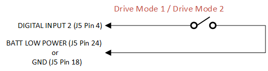
The figure below shows how to wire a drive mode selector switch to the controller. The drive mode selector switches between Mode 1 and Mode 2 (which are also referred to as Indoor and Outdoor). These modes can be individually programmed to provide different max speeds, accelerations, etc. When the switch is open, the controller is in Drive Mode 1; when the switch is closed, the controller is in Drive Mode 2.
Quickstop Switch Wiring
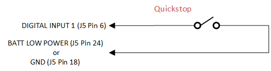
Depending on the module configuration, quickstop can be wired as active (+5 V) or passive (GND). The figure below shows how to wire a passive quickstop configuration. When the switch is closed, quickstop is activated. When the switch is open, quickstop is inhibited.
Note
In addition to the wired configuration there is a Qstop hi parameter that determines whether the Quickstop input is considered active high or active low. This parameter must be set correctly in order for the controller to function as expected. See Register 0318 for more information.
Forward/Reverse Switch Wiring
The figure below shows how to wire a Forward/Reverse switch to the controller. The forward/reverse switch changes the motor’s direction.
