Installation
The Phoenix Motor Controller may be supplied with or without an enclosure for protection against moisture and dust/dirt.
Use the following guidelines when wiring your motor controller.
General Wiring Guidelines
Cabling
- Keep cables as short as possible.
- Make sure the cabling you use can withstand the environment and stress points.
- Avoid using damaged cables; they can cause a fire.
- Avoid contact with flammable material.
- Install cables in such a way that users cannot reach them.
- If possible, do not route cables near the motor case.
- The wire size must be as large as possible. This reduces the resistance and electrical loss associated with the cable. Refer to the wiring sections for minimum wire sizes.
- Do not use wire sizes smaller than 0.5mm2/AWG20 for low current signals. Such wiring is not strong enough.
- Avoid wire loops, particularly loops of single wires instead of multiple wires.
- Run wires in pairs or bunches. Note that wires can come in bundles of two or three wires.
Connections
- The controller and speed setting potentiometers must be mechanically connected to the vehicle frame.
- The vehicle frame must not be used as the earth return. International safety standards prohibit any electrical low-resistance connection to the frame as a safety risk.
- Avoid the exposure of electrical connections. Insulate exposed connections.
- Use only the supplied terminal screws or nuts to make electrical connections.
- For CAN Bus connections, refer to additional guidelines found here
Warning
- Cable routing: When routing cables, you must route them in such a way as to prohibit water entry or undue stress or strain on the cables. Also, make sure the cables do not extend beyond the vehicle, and that they are not inhibited by a seat raise or other moving parts.
- Unit replacement: Before replacing or moving the motor controller, disconnect all the cables of the vehicle at the powered end.
- Service manual: The documentation that accompanies your end product should specify inspection and maintenance requirements for connectors and cables.
- Safety: The installer must make sure that the finished wiring is installed correctly and safely.
- Security: Disable the vehicle before making changes to the connections by: disconnecting the motor or batteries, or placing the drive wheels up off of the floor, or placing the battery circuit breaker in the open position.
- ISO requirements: Cover the battery and motor connectors with a cover that cannot be removed without certain tools, or otherwise install them such that they cannot be adjusted.
Mounting the Controller and Enclosure
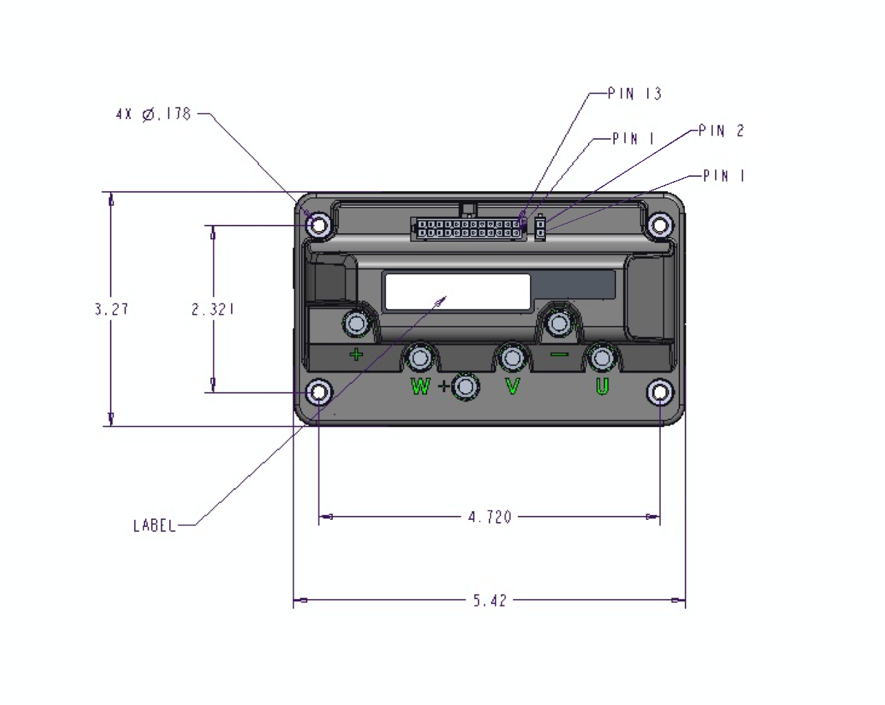
Phoenix motor controllers are equipped with four mounting holes, typically located at the corners of the unit. The mounting holes are sized for a #8 screw. The amount of torque on the mounting screws depends on the type of screw used. Consult the screw manufacturers specifications for torque information. The controller can be oriented in any position. It is recommended that the unit be positioned in a manner to keep it away from excessive dirt and moisture in order to prevent damage. Additionally, the installation location should have proper airflow to keep the ambient temperature below 45° C.
P125/P190 Mounting
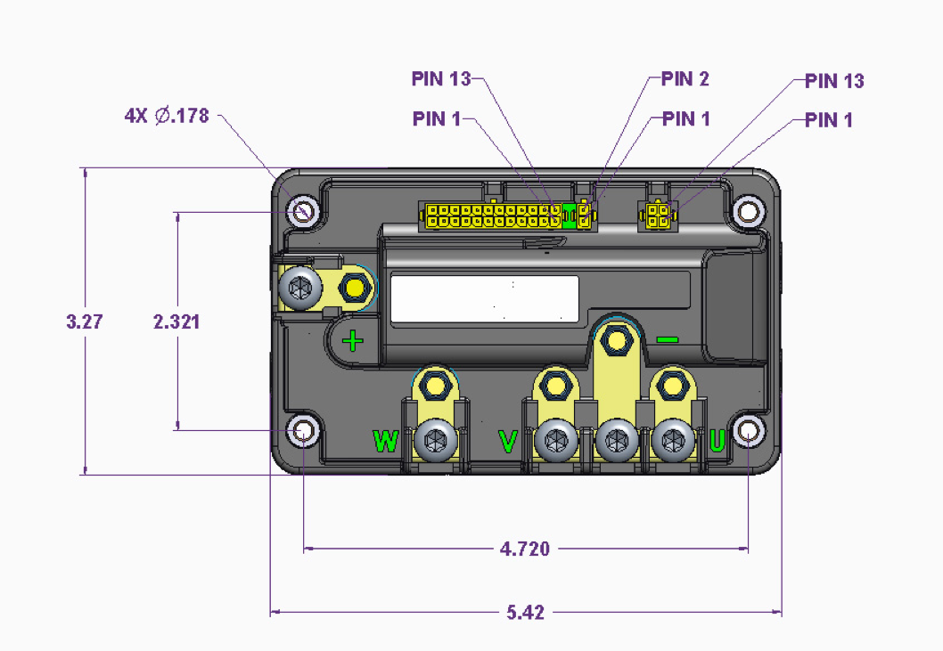
Motor and power connections should be made with properly sized wires and terminals, torqued to about 40-45 inch-pounds.
P250 Mounting
Motor and power connections should be made with properly sized wires and terminals, torqued to about 40-45 inch-pounds.
Connectors and Pinouts
Electrical connections vary among the various Phoenix models. Refer to the information below, or the custom specifications supplied with your controller.