Configuration Registers
Each configurable feature of the controller is defined by one or a combination of configuration register values. This table summarizes the available configuration registers.
These registers are available directly using the CAN Bus interface, and the ranges are those used natively by the controller. User Interface software may present the features or ranges differently (for example, representing a value as a percentage rather than 0-255). When using external software to configure the controller, refer to the external software's documentation for the correct values and ranges.
The operational configuration of the controller is stored permanently in the controller. At powerup, this configuration is copied to a 'shadow' version which is used thereafter. The CAN Bus interface is able to access both the permanent configuration and the shadow configuration. Changes made to the shadow configuration take effect immediately, but are not retained through a power cycle. Changes made to the permanent configuration do not take effect immediately, but are retained permanently. It is up to the system designer to determine whether to make a change permanent.
Danger
Adjusting or changing the controller's configuration can cause unexpected movement of the motor and/or vehicle/system. Always secure the machine before making adjustments to the configuration.
Configuration Registers
These registers are accessed using
- Bank 2, for shadow settings. The Modbus command address is 02xx. xx=register address
- Bank 3, for permanent settings. The Modbus command address is 03xx. xx=register address
See System Commands for details on writing motor registers.
All values are shown in hexadecimal format, unless otherwise noted. For example, Address 0319 refers to register 0x0319. Where a specific bit within a register is addressed, it is shown as rrrr:xx, where rrrr indicates the register in hexadecimal format, and xx indicates the bit number. Example, Address 0317:05 indicates bit 5 of register 0x17.
Note
Bits that are not defined or used should be left in their current state. Always read the register and then set or clear the bits you need to change and then write the new value back to the register.
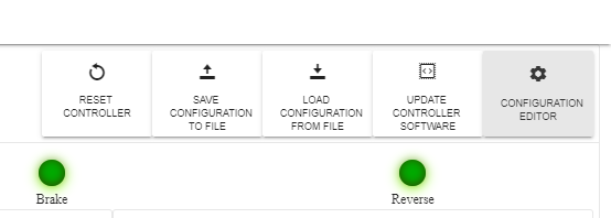
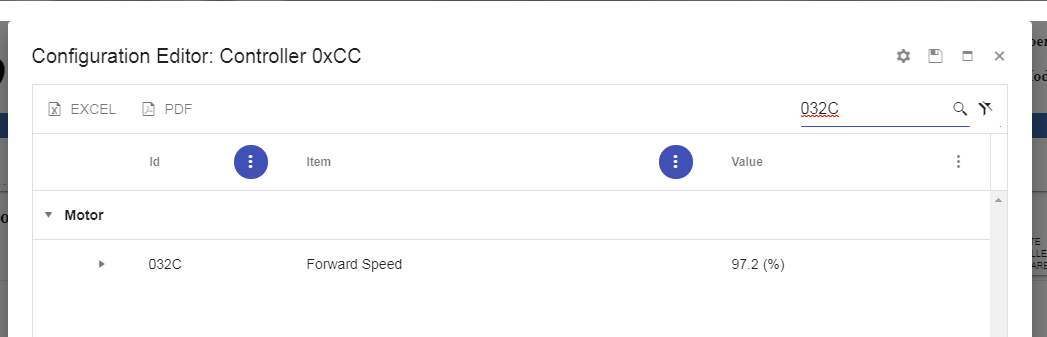
Configuration Editor
Using the Phoenix Diagnostics app is the easiest way to edit register settings. Simply click "CONFIGURATION EDITOR".
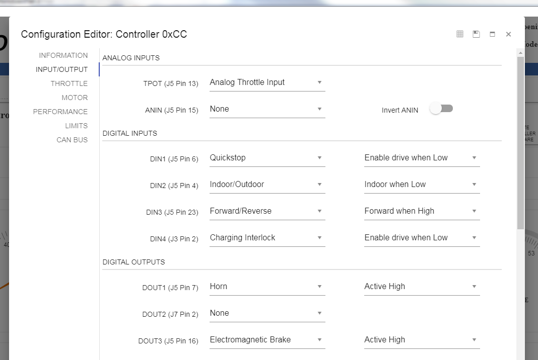
There are two modes for editing, "Normal" and "Advanced" . The mode that comes up is the "Normal" mode. This mode shows settings by category and has tools to aid in selection.
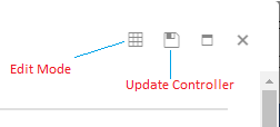
To edit a specific register in the "Advanced" mode click the table icon in the upper right corner.
In the "Advanced" mode you can pick a category and see all of the registers and their bit fields or values.
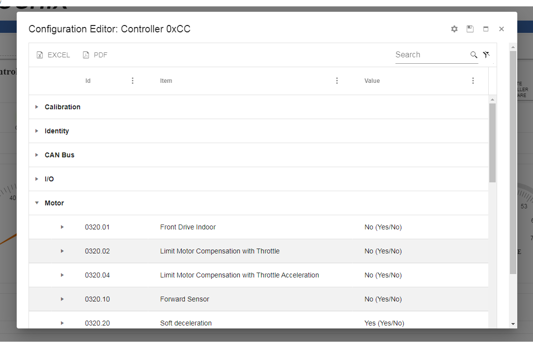
You can also search for a register such as "032C" to edit forward speed. Any values that are grayed out are restricted from editing.
Motor EEPROM (03) Registers
Here is a detailed list of common registers used to configure the controller.
| Addr. (Hex) |
Parameter | Format / Range |
Description |
|---|---|---|---|
| 0300 | Max Speed | Byte 0-255 |
Maximum speed used by some throttle modes. |
| 0315 | Hi Motor Temp Cutoff | Byte 0-255 |
Determines the voltage threshold of the ANALOG IN input. See Motor Temperature |
| 0316 | Hi Temp Cutoff | Degrees C + 0x6C 0-255 |
Determines the temperature at which the output power decreases to zero. See Controller Temperature |
| 0317 | Config Options 3 | Bitmap 0-1 |
Bit 5: Unidirectional Throttle Off/On. When 1, throttle causes motion in one direction only. |
| 0318 | Config Options |
Bitmap 0-1 |
Bit 0: 1=Beep when in reverse Bit 1: 1=Slow Quick Stop Bit 2: 1=Momentary contact on brake release Bit 3: 1=Key switch must turn off-on-off to power down Bit 4: 1=Lock enable, 0 digital throttle required before first movement Bit 5: Reserved Bit 6: Reserved Bit 7: 1=QSTOP high (Invert QSTOP signal) |
| 0319 | Throttle Deadband | 5V/256 ~=19.5mV 0-255 |
Sets the throttle pot range that the controller determines as neutral. 0=No deadband |
| 031B | Throttle Failband | 5V/256 ~=19.5mV 0-255 |
This is an area beyond the full speed throttle voltage that disables the motor. Throttle Failband provides a safety feature to protect against throttle shorts to ground or 5V, which could lead to dangerous runaways. 255=No failband. |
| 031D | Throttle Scale | 0-255 |
Sets the throttle scale which determines the throttle pot voltage needed for full speed, and sets the amount of throttle movement necessary to obtain full throttle. |
| 031F | Throttle Flags |
Bitmap 0-1 |
Bit 0: Invert Throttle. 1=Inverted throttle polarity Bit 1: Reserved Bit 2: Set to use ANALOG IN input as max speed Bit 3: Reserved Bit 4: Set to use max_spd setting in Register 0x00 Bit 5: Reserved Bit 6: Use Digital Throttle as Max Pot Bit 7: Reserved |
| 0320 | Motor Flags |
Bitmap 0-1 |
Bit 0-6: Reserved Bit 7: Set to disable the EM Brake feature |
| 0321 | Current Lower Boundary | Current 0-255 |
Defines the current lower limit for various current limiting features like motor temperature. The value is in 2.5A steps if using standard Phoenix controllers. For dual motor controllers it is 5A. |
| 0322 | Current Upper Boundary | Current 0-255 |
Defines the current upper limit for various current limiting features like motor temperature. The value is in 2.5A steps if using standard Phoenix controllers. For dual motor controllers it is 5A. |
| 0323 | Config Options 4 | 8 Bit 0-1 |
Bit 0: Indoor High 1=Indoor when high. 0=Indoor when low Bit 1: Zero throttle 0=2.5V Bidirectional 1=0V Unidirectional Bit 2: Reverse Pin 1=Active high 0=Active low Bit 5: In/Out current Bit 7: Motor Therm 1=Use ANALOG IN as motor temp sensor |
| 0327 | Top State Of Charge | Voltage 0-255 |
Defines the voltage at which state of charge is 100%. The value is in .35866V steps |
| 0328 | Undervoltage | 0.35866 V 0-255 |
Defines the voltage at which a low voltage warning will occur. |
| 032C | Forward PWM Scaling Outdoor |
%PWM 0-255 |
Forward PWM scaling value (outdoor forward speed) |
| 032D | Reverse PWM Scaling Outdoor |
%PWM 0-255 |
Reverse PWM scaling value (outdoor reverse speed) |
| 032E | Forward PWM Scaling Indoor |
%PWM 0-255 |
Forward PWM scaling value (indoor forward speed) |
| 032F | Reverse PWM Scaling Indoor |
%PWM 0-255 |
Reverse PWM scaling value (indoor reverse speed) |
| 0335 | EM Brake Time |
Time Constant 0-255 |
Brake delay |
| 0336 | Forward Acceleration (Outdoor) |
Time Constant 0-255 |
Forward acceleration constant. The higher the number the longer the time. The formula to convert to seconds is 40.8/(255-x), so a value of 0xD8 results in a PWM ramp of about 1 second. |
| 0337 | Forward Deceleration (Outdoor) |
Time Constant 0-255 |
Forward deceleration constant. The higher the number the longer the time. |
| 0338 | Forward Deceleration (Outdoor) |
Time Constant 0-255 |
Forward deceleration constant. The higher the number the longer the time. |
| 0339 | Reverse Acceleration (Outdoor) |
Time Constant 0-255 |
Reverse acceleration constant. The higher the number the longer the time. |
| 033A | Reverse Deceleration (Outdoor) |
Time Constant 0-255 |
Reverse deceleration constant. The higher the number the longer the time. |
| 033B | Reverse Deceleration (Outdoor) |
Time Constant 0-255 |
Reverse deceleration constant. The higher the number the longer the time. |
| 033C | Forward Acceleration (Indoor) |
Time Constant 0-255 |
Forward acceleration constant. The higher the number the longer the time. |
| 033D | Forward Deceleration (Indoor) |
Time Constant 0-255 |
Forward deceleration constant. The higher the number the longer the time. |
| 033E | Forward Deceleration (Indoor) |
Time Constant 0-255 |
Forward deceleration constant. The higher the number the longer the time. |
| 033F | Reverse Acceleration (Indoor) |
Time Constant 0-255 |
Reverse acceleration constant. The higher the number the longer the time. |
| 0340 | Reverse Deceleration (Indoor) |
Time Constant 0-255 |
Reverse deceleration constant. The higher the number the longer the time. |
| 0341 | Reverse Deceleration (Indoor) |
Time Constant 0-255 |
Reverse deceleration constant. The higher the number the longer the time. > |
| 034D | Configuration Flags |
Bitmap | Bit 3: Clear to disable power-on diagnostics. |
| 034E | Over Current Timeout | Current 0-255 |
Defines the time before action is taken if an amperage boundary is exceeded. The value is in 5A steps if using standard Phoenix controllers. For dual motor controllers it is 2.5A. |
| 0353 | Digital Control | Bitmap 0-1 |
Bit 0: Reserved (set to 0) Bit 2: Trigger a fault if throttle is not in neutral position at startup Bit 3: Trigger a fault on Quickstop (require keyswitch to clear) Bit 4-7: Reserved (set to 0) |
| 0357 | Options 6 | Bitmap 0-1 |
Bit 0: Enable digital control (buttons) Bit 1: Disable THROTTLE POT CENTER (analog) throttle Bit 2: Enable Digital Throttle Bit 3: Invert digital throttle (when set, 0xFF throttle means slow, 0 throttle = fast) Bits 4-7: Reserved |
| 035B | Severe Undervoltage | 0.35866V 0-255 |
Defines the low voltage threshold. If the input voltage remains below this value for a period of time, the controller will power off. Note that the controller will not power on unless the input voltage is at least as high as indicated by this setting. |
| 035C | IN1 Type | Bitmap Enum |
Switch 1 usage, set upper nibble to '1' to enable ANALOG IN as a temperature 'stop' signal for external motor temperature sensing |
| 035D | IN23 Type | Bitmap | set upper nibble to 'A' to enable 'in2' as a seat stop input. Otherwise, set to 0 |
| 035E | Config Options 9 | Bitmap 0-1 |
Bit 2: in2_invert 0 = seat occupied when DIGITAL INPUT 2 = 1, 1 = occupied when DIGITAL INPUT 2 = 0. |
| 035F | Throttle Offset | 5V/256 ~=19.5mV -128 - 127 |
Sets the throttle offset for bidirectional throttles so that the center voltage is offset higher or lower than 2.5V. |
| 0386 | Config Options 8 | Bitmap 0-1 |
Bit 5: Aggressive temperature cutback. When set, the controller will begin cutting back power at 32 degrees below the temperature limit, rather than 8 degrees C. |
| 0387 | High Voltage Limit | Voltage 0-255 |
Limit where battery voltage is too high to operate. The value is in .35866V steps |
| 0388 | Motor Type | Bitmap | Bit 0-2: Number of motor pole-pairs Bit 4-5: Sensor geometry: 0: Type 1 1: Type 1A 2: Type 2 3: Type 2A Bit 6: If true, swaps sensors A and C Bit 7: sent if sensors are normally low |
| 038A 0x038B |
Max RPM 16-bit Little Endian |
0- 32767 | BLDC Prior to V1.7.1 Bit 15: Enable Speed Limit. Bits 0-14: Speed limit in RPM. If enabled, this feature cuts back motor power to keep BLDC motor RPM below the indicated value. Zero=No speed limit. BLDC As of V1.7.1 This value is the target RPM only. Use RPM Config Register to define the operation. |
| 038C | RPM Config | Bitmap | BLDC as of V1.7.1 Brushed as of 1.7.8 BITS 3:0 0: No Speed Loop or Speed Limit 1: Speed loop (speed loop enabled if target RPM != 0) 2: Speed Limit - single limit (specified in Addr 0x8B-8A) 3: Speed Limit - auto-capture (will transition back to 2 after capture) 4: Throttle re-scaling during speed limit. 0: disabled 1: enabled (uses max_spd) BITS 5:7 Reserved |
| 038F | Current Limit Config | Bitmap | Bit 7: Enable current limiting Bit 6: Current time Units (0 = seconds, 1 = minutes) Bit 5: Adjust Current Limit Threshold for FET temperature (0 = disabled, 1 = enabled) Bit 4: Adjust Current Measurement for FET temperature (0 = disabled, 1 = enabled) Bit 0-3: Mode (See Motor Current Limiting) 0 = Step Mode 0 1 = Step Mode 1 2 = StepMode 2 3 = External Motor Temperature 4 = Incremental Mode 0 5 = Incremental Mode 1 6 = Incremental Mode 2 7 = Incremental Mode 3 8-13 = Reserved 14 = Step Stop Mode 15 = In/Out Mode |
| 0392 | GPIO Config 2 |
Bitmap | Normally 0, set upper nibble to '1' to enable ANALOG IN input as a temperature 'stop' signal |
| 039B | ANALOG IN Temperature Offset | Byte 0-255 |
This value represents the ANALOG IN voltage if the temperature were 0 degrees C. The Range of offset is (0.625 - 1.92V) |
| 039C | ANALOG IN Temperature Gain | Byte 0-255 |
ANALOG IN scaling factor(bits6:0). Bit 7: 0=positive volt/temp, 1=negative volt/temp |
CAN Bus EEPROM (04) Registers
Here is a detailed list of registers used to configure the CAN bus operation.
| Address (Hex) |
Parameter | Range | Description |
|---|---|---|---|
| 0400 | CAN Bus ID Low | 0-255 | Lowest allowed ID. If ID is set lower than this value the ID will be coerced to this value. |
| 0401 | CAN Bus ID High | 0-255 | Highest allowed ID. If ID is set higher than this value the ID will be coerced to this value. |
| 0402 | CAN ID | 0-255 | CAN Bus ID |
| 0403-040A | Reserved | 0-255 | Do not modify. |
| 040B | CAN Baud | 0-3 | CAN Bus Baud Rate 0=125K 1=250K 2=500K 3=1Meg |
| 040C | CAN Bus Priority | 0-7 | CAN Bus Message Priority |
| 040D-040E | Reserved | 0-255 | Do not modify. |
| 040F | Digital Control Low Byte Motor #1 |
0-255 | Digital Control Options (LSB) Bit 0-3: Reserved Bit 4: 0=Disable digital control 1=Enable digital control Bit 5: 1=Digital Stop (Quick Stop) on comm loss Bit 6: 1=Set digital throttle to 0 on comm loss. Bit 7: 1=Turn off digital brake on comm loss. |
| 0410 | Digital Control High Byte Motor #1 |
0-255 | Digital Control Options (MSB) Bit 0: 1=If digital (0x50) commands are sent and register 0x0357 is not set for digital control that feature is temporarily enabled as long as 0x50 commands are being received. This is for use if both analog and digital (CAN Bus) throttle are used. NOTE: Digital throttle will override the analog throttle but as soon as commands stop the analog throttle resumes control Bit 1: 1=Turn off digital horn on comm loss. Bit 4: 1=Echo digital throttle (0x50) commands back to host. |
| 0411 | Status Message Enable | 0-255 | Each bit that is set enables the corresponding status message. Example: bit 2 enables the FF02 status message. |
| 0412-0425 | Timers 0-19 | .05-2.55 seconds |
Sets various timers in units of 10 milliseconds. NOTE: setting a timer to 0xFF causes it to reset to the factory default after the next power cycle. See Timer Configuration for more info. Timer 0: FF00 Status Rate Timer 1: FF01 Status Rate Timer 2: FF02 Status Rate Timer 3: FF03 Status Rate Timer 4: FF04 Status Rate Timer 5: FF05 Status Rate Timer 6: FF06 Status Rate Timer 7: FF07 Status Rate Timers 8-13: Reserved Timer 14: Motor 1 digital throttle timeout Timer 15: CAN Bus Alarm timeout Timer 16: Reserved Timer 17: Motor 2 digital throttle timeout Timers 18-19: Reserved |
| 0426-0428 | Reserved | 0-255 | Do not modify. |
| 0429 | Digital Control Low Byte Motor #2 |
0-255 | Digital Control Options (LSB) Bit 0-3: Reserved Bit 4: 0=Disable digital control 1=Enable digital control Bit 5: 1=Digital Stop (Quick Stop) on comm loss Bit 6: 1=Set digital throttle to 0 on comm loss. Bit 7: 1=Turn off digital brake on comm loss. |
| 042A | Digital Control High Byte Motor #2 |
0-255 | Digital Control Options (MSB) Bit 0: 1=If digital (0x50) commands are sent and register 0x0357 is not set for digital control that feature is temporarily enabled as long as 0x50 commands are being received. This is for use if both analog and digital (CAN Bus) throttle are used. NOTE: Digital throttle will override the analog throttle but as soon as commands stop the analog throttle resumes control Bit 1: 1=Turn off digital horn on comm loss. Bit 4: 1=Echo digital throttle (0x50) commands back to host. |
| 042B-044A | Reserved | 0-255 | Custom Status (Version 4.5.0 and above). See Custom Status Configuration for more info. |
| 044B | Reserved | 0-255 | Bootloader Version MAJOR Version 4.5.0 and above |
| 044C | Reserved | 0-255 | Bootloader Version MINOR Version 4.5.0 and above |
| 044D | Reserved | 0-255 | Bootloader Version PATCH Version 4.5.0 and above |
| 044E | Reserved | 0-255 | CAN Bus Processor Version MAJOR Version 4.5.0 and above |
| 044F | Reserved | 0-255 | CAN Bus Processor Version MINOR Version 4.5.0 and above |
| 0450 | Reserved | 0-255 | CAN Bus Processor Version PATCH Version 4.5.0 and above |