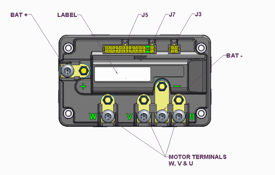
P125/P190 Pinout
Connectors and Mates
| Label | Type | Function | Part Number | Mate |
|---|---|---|---|---|
| J7 | 2 Pin TE Micro MATE-N-LOK | EM Brake | TE 3-794630-2 | TE 794617-2 |
| J3 | 4-Pin TE Micro MATE-N-LOK | Charging | TE 3-794630-4 | TE 794617-4 |
| J5 | 24-pin TE Micro MATE-N-LOK | Control and Status I/O | TE 5-794630-4 | TE 2-794617-4 |
| + (Battery +) |
STUD M6 X 1 8MM | Positive voltage input | ||
| – (Battery -) |
STUD M6 X 1 8MM | Negative voltage input | ||
| W (Motor W) |
STUD M6 X 1 8MM | High current connection to motor | ||
| V (Motor V) |
STUD M6 X 1 8MM | High current connection to motor | ||
| U (Motor U) |
STUD M6 X 1 8MM | High current connection to motor |
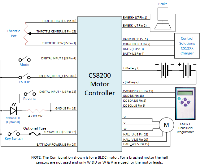
J7 Brake

| Pin | Name | Description | Typical Use |
|---|---|---|---|
| 1 | EMBRK+ | VIN | EM Brake High Voltage |
| 2 | EMBRK- | < .4V , 1.25 A Max | EM Brake Ground |
J3 Charging
| Pin | Name | Description | Typical Use |
|---|---|---|---|
| 1 | Raise Charge | Active < 0.8VDC | |
| 2 | Charging | Active > 2VDC | |
| 3 | Batt - | <0.02VDC | Charger Battery - |
| 4 | Batt + | >28.7VDC @3A | Charger Battery + |
J5 Control and Status I/O

| Pin | Name | Description | Typical Use |
|---|---|---|---|
| 1 | THROTTLE LOW | Throttle Pot Low (~0V): Low potentiometer reference for an analog throttle. | Throttle potentiometer |
| 2 | CAN-H | CAN Bus High (5 volt differential) | Status/Configuration |
| 3 | CAN-L | CAN Bus Low (5 volt differential) | Status/Configuration |
| 4 | DIGITAL INPUT 2 (GP_DIN2) |
Digital Configurable Input 2 | Seat Switch |
| 5 | NC | ||
| 6 | DIGITAL INPUT 1 (GP_DIN1) |
Digital Configurable Input 1 | Fault Input (Quickstop) |
| 7 | DIGITAL OUTPUT 1 |
Open Collector Output. Active > 2 V, Inactive = open circuit | |
| 8 | I2C SDA | I2C Data | Status/Configuration |
| 9 | I2C SCL | I2C Clock | Status/Configuration |
| 10 | THROTTLE POT HIGH | Throttle Pot High (~5V): High potentiometer reference for an analog throttle. | Throttle potentiometer |
| 11 | 5V SUPPLY | Regulated 5V Supply | Motor Hall Sensor Power |
| 12 | 15V SUPPLY | Regulated 15V Supply | Motor Hall Sensor Power |
| 13 | THROTTLE POT CENTER | Throttle Pot Center (0-5VDC) | Throttle potentiometer |
| 14 | KEY SWITCH LOW | Active < .8V, Inactive = open circuit | Keyswitch, see also KEY SWITCH HIGH |
| 15 | ANALOG IN | Analog Configurable Input | Temperature Sensor or Max speed pot |
| 16 | DIGITAL OUTPUT 3 |
Digital output. Requires mezzanine board customization to use this signal | Typically used as "Raise Charge" signal |
| 17 | DIGITAL OUTPUT 4 |
Digital output. Requires mezzanine board customization to use this signal | Typically used as "Brake Release" |
| 18 | GND | < 0.2 v with respect to GND | System Logic Ground |
| 19 | HALL W | Sensor position | Motor Hall Sensor W |
| 20 | HALL V | Sensor position | Motor Hall Sensor V |
| 21 | HALL U | Sensor position | Motor Hall Sensor U |
| 22 | KEY SWITCH HIGH | Active > 2 V, Inactive = open circuit | Keyswitch, see also KEY SWITCH LOW |
| 23 | DIGITAL INPUT 4 (REVERSE) |
Digital Configurable Input 4 | Forward/Reverse Control |
| 24 | BATT LOW POWER | ~VIN+, <1A. Current Protected Battery (+) Output | Used for KEY SWITCH HIGH |
Battery Connections
The P125/P190 battery connections are made using the supplied M6, Torx T30 screws. A ring terminal such as TE Connectivity part number 321598 can be used to terminate the leads. Connections should be torqued to 40-45 inch-lbs.
Warning
Do not overtighten the terminal connections. Torque to 20 inch-pounds. Overtightening may cause damage to the controller.
Motor Terminals
The P125/P190 motor connections are made using the supplied M6, Torx T30 screws. A ring terminal such as TE Connectivity part number 321598 can be used to terminate the leads. Connections should be torqued to 40-45 inch-lbs.
Note
For a Brushed motor with only two motor connections, use the 'W' and 'U' connections
Warning
Do not overtighten the terminal connections. Torque to 20 inch-pounds. Overtightening may cause damage to the controller.
P125/P190 Typical Connections